Figure 1: Data from Tinius Olsen hydraulic test
Analysis Introduction
There are the initial requirements for the project.
-
Require roller speed to be under 100 RPM
-
Cannot cost more than 2500 dollars for materials and manufacturing
-
Device cannot weigh more than 75 pounds
-
Must delaminate composite
Preliminary Sketches
This section will detail the first preliminary sketches of proposed composite devices.
Figure 1 below shows the very first idea for the composite bender. This is an idea for a jig to hold the composite in place while conducting bending and crushing testing. The idea is to have interchangeable holders for the composite depending on if bending or crushing is taking place.
Figure 1: Initial bending device
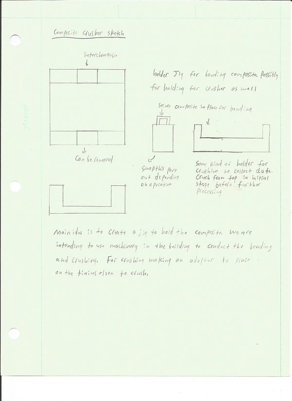
Figure 1: Original sketch for delamination device
Figure 2, 3 and 4 below show the initial calculation for the dimensions needed for the composite holder

Figure 2: Calculation for composite bender

Figure 3: Continuation of calculation

Figure 4: Conclusion of calculation
Figure 5 below shows the first CAD file created for the composite bending idea

Figure 5: CAD file for composite holder
Hydraulic Press Tests
This section will detail the first tests done to bend the composite using the Tinius Olsen hydraulic press. The purpose of these tests was to determine how much force was required to delaminte the composite.
Figure 1 below describes the first compression test using a three point bend on the Tinius Olsen hydraulic press. The load to cause the composite to fail was around 10,000 pounds. This became the benchmark for future designs.

The composite recycling project is primarily based around two processes. The first process is to delaminate or split the solid composite into layers. The second process is to cut the delaminated composite into strips. This section will explore the load required to delaminate the composite as well as the process of developing the delaminating device.
Figure 2 and 3 below describe flexure bending stress calculations on the composite. This was used to determine the bending stress required to delaminate the composite and would be used in future design.

Figure 2: Bending stress calculation

Figure 3: Bending stress calculation conclusion
Final Sketches
This section will detail the final build of the composite delaminating device
Figure 1 shows the first sketch of the composite delaminator. The basic shape remainded the same although many iterations of this device would be developed before a final design was chosen.

Figure 1: First drawing of composite delaminating device
Figure 2 below shows the first version of the complete composite holder. The major change to this design was the rotating cam shown at position 2. This was deemed extremely difficult to machine so removable cams were chosen instead of one solid cam.

Figure 2: First version of the composite delaminating device
Figure 3 below shows the first proposed final assembly for the delamination device. This differs from Figure 4 below in that the sides are taller which increases the overall height of the device. The reason this was changed is the material ordered was the incorrect length.

Figure 3: Second version of the composite delaminating device
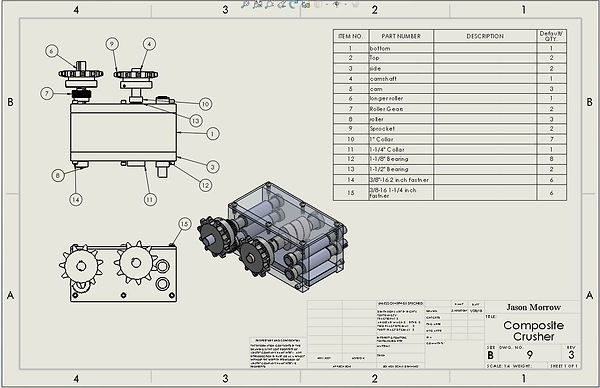
Figure 4: Third version of the composite delaminating device
Figure 5 below is the final version of the delaminating device. The major changes are slots to adjust the height of the rollers and the distance for the chain connecting the camshaft to the rollers

Figure 5: Final version of the composite delaminating device
The primary analysis of this project involved investigating the forces required to damage the composite matrix so it could be cut. This was initially done by placing composite samples into a three point bend jig and utilizing a hydraulic press to determine the load required to damage the composite. This value could be used to determine how much force a device would need to generate.
From this test it was concluded the easiest method to bend the composite is to use rotating cams and rollers as the material feeds through. The most important requirements were staying under the $5,000 budget and reducing the RPM to under 100. The lower the RPM the higher the torque and thus higher the force but at the cost of the material feeding too slowly. The balance was found at reducing the 1750 RPM from the motor to 88 RPM using a 20:1 gearbox reducer.